• Welcome to the new COTI server. We've moved the Citizens to a new server. Please let us know in the COTI Website issue forum if you find any problems.

CT Only: Type T Deckplans, Fixed

Grav_Moped

SOC-14 5K
Admin Award 2022
Knight
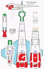
This is a month-long project (see COTI thread Fixing the Type T Deck Plans?) provoked by the discovery that the deck plans provided in FASA's Adventure Class Ships, Vol. II for the Type T Patrol Cruiser did not match the illustration on the cover of the box. Not only that, but also they didn't match the description of the Type T Patrol Cruiser given in LBB2 '81, p. 20. Further, the plans themselves, while satisfactory for most situations in which player characters would interact with a ship of that class, do not represent a usable layout for the hypothetical crew working aboard it – for example, they lack common spaces such as wardrooms and galleys.

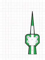
What follows is my interpretation of that cover illustration.
It's likely quite similar to the deck plans upon which that illustration was based, with a few minor changes. The first is that I've provided individual cabins for each flight crew member including the gunners (who are double-bunked in the LBB2 description, and almost certainly were on those plans as well) while retaining the same overall crew space (40Td, or 10 stateroom-equivalents) for those personnel. The second is that I've interpreted the layout as being a split-level design, with the flight deck and foredeck at a level halfway between the upper and lower mid/aft decks. (In the original plans, the foredeck's vertical offset might have involved stairs or stair-step floor height changes rather than an elevator.) The third change is that I've moved the Low Passage Berths from behind the flight deck to the aft end of the ship's troops' barracks on the lower deck.

Notably, the ACS Vol. II deck plans moved the Ship's Boat from underslung external grapples into the clamshell bay at the aft end of the top deck, and the GCarrier from that clamshell bay to one just forward of it. These revised plans have reversed those re-locations.
Except for the lateral section view, the plans are in 0.25"=1.5m scale. The lateral section view is half-sized (0.25"=3m).

Subsequent plan elements in this thread are natively* 0.5"=1.5m (suitable for 28mm figures when printed out at full size, and each section can be printed on 8.5"x11" paper within the printable area of the sheet).
T Poster.jpg
------------------

*Right-click and open image in new page, then save the image from there.
 
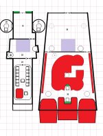
Nose Section

T Nose.jpg
Description:

1. Crawlspace
Avionics access. This area is at most 1.5m tall, tapering to 1m tall at the forward end.

2. Flight Deck
This section is comprised of a pair of domes, one over each fore-aft pair of control couches. There is a small forward-facing windshield above the access hatch to the forward avionics crawlspace.

The control couches are for the Astrogator (left forward), Pilot (right forward), Lead Gunner (left aft, manning optional), and Chief Engineer (right aft, manning optional). The aft two consoles can be repurposed for remote control of the turrets if desired to support fire as 2 batteries under High Guard rules. In this arrangement the missile turrets require two additional personnel at the magazine to reload them after three salvos to conform to LBB2 crew size rules.

3. Computer
This is the ship's Model/3 computer.

The flight deck is a direct copy from the FASA plans. It only really needs two control couches though, so I needed to justify the other two seats somehow. Also, I'm not entirely sure that it "works" geometrically – there might not be enough room to get under the inboard edges of the "bubble cockpits" as it's drawn – but it looks cool and I'm trying not to change too much here.
 
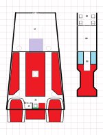
Foredeck and Upper Crew Quarters Section

T Fore UpCrew.jpg

4 and 5. Storage Lockers
These lockers are about 1.5m tall due to the shape of the hull. They contain a variety of equipment ranging from vacc suits to folding furniture.

6. Head
Toilet and sink, for use by bridge crew.

7. Wardroom
This space usually has a small table and four chairs set up. These can be stowed in the lockers nearby, and there are additional folding chairs available if needed. There are comfortable couches (that also can fold away) along the side bulkheads.

8. Stateroom
Single occupancy. Includes a fold-away desk, folding chair, and retractable fresher (toilet, sink, spray hose for showering), as do all staterooms except for the barracks on the lower deck. The bed can also be stowed.

The port-side hatch from area 10 does not provide access to this stateroom; instead, it leads to the port laser turret located above it.

This is typically the Pilot's stateroom.

9. Stateroom
Single occupancy (see 8, above).

The outboard starboard-side hatch from area 10 does not provide access to this stateroom; instead, it leads to the starboard laser turret located above it. The inboard starboard-side hatch symbol represents the emergency elevator bypass hatches from the upper and lower mid-decks (see Section A-A, adjacent) and these hatches do provide access to this stateroom. These bypass hatches are electrically locked while the elevator is operational, though this lockout can be overriden from the flight deck or from the drive bay.

This is typically the Navigator's stateroom.

Elevator (not numbered; lavender square between 8 and 9)
Connects foredeck, and upper and lower mid-decks. (Note that the foredeck is vertically halfway between the two mid-decks -- see the section view for a better visualization.) The elevator car is not airtight, though the external doors to the elevator shaft at each level are. The elevator shaft can serve as an airlock between those three sections if needed. In the event of an elevator malfunction, the emergency bypass hatches into the starboard forward stateroom (9) unlock automatically.

10. Common Area
Contains ready food storage and galley, as well as folding chairs and tables. Most meals are served here, and it is the normal location for crew meetings.

11. Head
Toilet and sink, for crew use. Note that each stateroom also includes a basic fold-away fresher.

12-17. Staterooms
Single occupancy (see 8, above).

12: Gunner
13: Gunner
14: Engineer
15: Engineer
16: Medic (Note: if a patient in the Med Bay needs full-time care, the Medic will temporarily swap rooms with one of the two gunners on the lower mid-deck).
17: Chief Engineer

Ceiling hatch in hallway between staterooms 14 &15 leads to electronics access space (18) in Top Deck.

18. (in Top Deck, above upper mid-deck)
Electronics access space. Low ceiling. Floor hatch leads to hallway between 14 & 15. Aft hatch leads to missile magazine (19).
 
Top Deck and Upper Cargo Hold/Upper Drive Bay
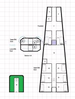
T Up Cargo Drives Attic.jpg
Top Deck

19. Magazine

Missile storage for the two aft turrets (20 & 21).

20 and 21. Missile Turrets
Access is via the iris valves in the ceiling of the upper cargo hold.
Access panels in turrets are for missile loading, not personnel access.

22. Loading Bay
The entire roof of this compartment opens to the exterior. There is a retractable docking tube around the roof hatch, with standard couplings.
Lavender square is freight elevator to upper and lower cargo hold.
Starboard floor iris valve leads to upper cargo hold.
Port aft floor hatch leads to upper drive bay.

23. GCarrier Bay
Stores a standard GCarrier.
Roof and aft walls swing upward as a clamshell door.

(Note: Numbering break is intentional)

Upper-Mid Deck
35. Upper Cargo Hold

Ceiling iris valves port and starboard lead to the missile turrets.
Aft port floor iris valve (there is none there on the ceiling) leads to Lower Cargo Hold (37), as does the one on the starboard side. Starboard aft ceiling iris valve leads to the top deck Loading Bay (22).
Lavender square is the cargo elevator. Grey outline is a portion of the deck that can be retracted/removed to facilitate offloading oversized cargo from the Ship's Boat.

36. Upper Drive Bay
Primarily contains the Power Plant (center) and Maneuver Drives (outboard, aft), but elements of the Jump Drive are along the port and starboard bulkheads and in a block in the aft center.

The forward-facing control couch is the primary Power Plant control, while the aft-facing one is for the Maneuver Drive.

The ceiling hatch forward port-side leads to the top deck Loading Bay. The floor iris valves port and starboard aft lead to the Lower Drive Bay (38). The floor iris valve in the middle of the Power Plant is accessible by an awkward low crawl under the Power Plant as shown; it leads to an otherwise inaccessible part of the Jump Drive in the Lower Drive Bay (38).
 
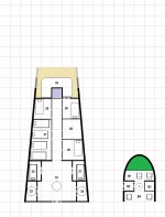
Lower Crew Deck
T LowCrew.jpg
Lower Crew Deck

24. Life Support Crawlspace

Accessible from maintenance hatch in stateroom (25), not accessible from hatch in stateroom (26).
Very low ceiling.

Elevator (lavender square) described previously.

25. Stateroom
Gunner.

26. Stateroom
Hatch in forward bulkhead leads to stateroom (9). Hatch is electrically locked unless elevator malfunctions. See description of room 9 for details.

Gunner.

If a patient in the Med Bay (29) requires close attention, the medic will swap rooms with the gunner in this stateroom.

27: Barracks
Open-bay barracks for 8 ship's troops. Bunks can be folded away.

28. Gang Head
Has two toilets and two shower stalls.

29. Med Bay.
Contains two bunks, one of which is normally stowed. Tech-level appropriate medical equipment is present.

30 &31. Low Berths
Each compartment contains two low berths. The hatches have pressurization interlocks, and each compartment has two basic rescue vacc suits each.

32. Ready Room
This serves as the common area for the ship's troops. The lockers n the aft bulkhead are airtight, but not sturdy.

The floor iris valve is covered by a pressure-tight maintenance hatch.

The entire room can serve as a ventral airlock if the Ship's Boat is not present, or as an airlock to the lower cargo hold.

33. Airlock
Exits below wing, port side. This airlock has a retractable stairway, exiting aft.

34. Airlock
Exits below wing, starboard side. This airlock has a retractable docking tube. The starboard side landing gear pads include magnetic grapples to facilitate docking with other ships.

Ship's Boat (B1-4; B5-6 separate sheet)
Descriptions follow descriptions of remaining ship locations.
 
Lower Cargo Hold and Lower Drive Bay, and Ship's Boat

T LowCargo Drives Boat.jpg
37. Lower Cargo Hold
Both ceiling iris valves, aft, lead to the Upper Cargo Hold (35).

The lavender square is the freight elevator.

The grey outline is the floor cargo hatch (this includes the area of the freight elevator). If the Ship's Boat is docked and rotated so its side hatches face the ship, this leads to the Ship's Boat's cargo hold (B5). If it is docked and rotated so its roof hatch faces the ship, this hatch is blocked. If the Ship's Boat is not docked, this opens to the exterior.

There is no direct access to the Lower Drive Bay (38) from the Lower Cargo Hold.

38. Lower Drive Bay
Primarily contains the Jump Drive, but the Maneuver Drives protrude into this deck from above.

Port and starboard ceiling iris valves lead to the Upper Drive Bay. Iris valve in center of Jump Drive leads to underside of Power Plant and and an awkward low crawl under it; there is no other way to get to the open space in the center of the Jump Drive unit.

39. Head
Toilet and sink, for use of Engineering crew. Airtight seal to allow use while drive bay is depressurized.

Ship's Boat (B1-6)
This is a standard 30-ton Ship's Boat from LBB2 and Supplement 7, Traders and Gunboats. The only modification is the addition of a roof hatch between the airlock and the head.

B1. Flight Deck
Pilot in right seat, gunner or navigator in center seat.

B2. Airlock

B3. Head

Toilet, sink, and spray hose for crew use.

B4. Passenger Compartment
Seats 6. Seats can fold and stow to allow transporting an additional 3 tons of cargo.

B5. Cargo Compartment
6 Tons of cargo capacity, maximum cargo dimensions 4.5m x 6m x 3m.

B6. Drives Access.
 
About the Ship's Boat...
B4. Passenger Compartment
Seats 6. Seats can fold and stow to allow transporting an additional 3 tons of cargo.

B5. Cargo Compartment
6 Tons of cargo capacity, maximum cargo dimensions 4.5m x 6m x 3m.
Note that these figures do not reflect the LBB2 '81 version of the Ship's Boat, which has 13.7Td of free space. Even if armed and equipped with a Mod/1 computer, there should be a total of 11.7Td free in the '81 version, where the S7 version (presumably LBB2 '77) only has 9Td available (6Td cargo, 3Td of Small Craft Couches).

This suggests that despite appearances, the Ship's Boat should be able to transport the Type T's GCarrier if post-1977 rules are in effect. This might be accomplished by packing the passenger seats in a bit more closely and moving the aft passenger cabin bulkhead forward by 1.5m, and extending the port cargo bay door forward by a similar amount. I'm not redrawing it, though.
 
Last edited:
I believe I attempted to point out (once or twice) that it would be optimal to be able to load the G-Carrier into the Ship's Boat for orbit to surface interface ops. :rolleyes:
 
I believe I attempted to point out (once or twice) that it would be optimal to be able to load the G-Carrier into the Ship's Boat for orbit to surface interface ops. :rolleyes:
It'd be nice.

Using later rules and adjusting the design appropriately would likely change the exterior lines (why have a separate topside parking bay for the GCarrier when it should be in the cargo hold next to the hatch to the Ship's Boat?) and I wanted to avoid that.

Limiting the design to contemporaneous canon assets and images (as I did here), this is what you get.

This can be worked around in the ongoing PbP, which is using LBB2 '81.
 
Last edited:
Except for the lateral section view, the plans are in 0.25"=1.5m scale. The lateral section view is half-sized (0.25"=3m).

Subsequent plan elements in this thread are natively* 0.5"=1.5m (suitable for 28mm figures when printed out at full size, and each section can be printed on 8.5"x11" paper within the printable area of the sheet).
Check the margin capability of your printer, though. You may need to crop off 1/4" from each side on the "poster" version to get it to print on (US-standard) 8.5"x14" Legal paper* -- I ended up having to do this myself with an older printer. I think the 1/2"=3m plan elements are ok, though.

-------------
*I didn't have any Legal paper (and couldn't find any in office-supply stores, either) so I had to make it myself by cutting and splicing sheets.

Call it pro se Legal paper, if you will.
 
A bit late to the party, but I absolutely love the amount of detail you have put into this! Excellent work! This is how deck plans ought to be made. Two thumbs up!
 
A bit late to the party, but I absolutely love the amount of detail you have put into this! Excellent work! This is how deck plans ought to be made. Two thumbs up!
Thank you. It was a fun project, and I had a lot of help.
 
Last edited:
Once you have recovered I hope you have a crack at another ship. Good work :)
Thanks! I'm open to suggestions. Know of any other ships where the canon illustrations don't match the canon deck plans? Or ones where there aren't any, or you just don't like the canon deck plans for some reason... :)

Otherwise, I'm vaguely interested in re-doing more canon ships as tailsitters (fortunately, the Mercenary Cruiser is already taken care of... LOL)
 
Otherwise, I'm vaguely interested in re-doing more canon ships as tailsitters (fortunately, the Mercenary Cruiser is already taken care of... LOL)
Ooh, this would be grand! I've been wanting to use tail-sitters IMTU for some time, but have stayed with the belly-landing canon ones as I'm no good at drawing deckplans. My "grand plan" for MTU is one where all ships are built "like rockets" and there are no inertial dampeners/compensators or reactionless thrusters, instead ships are using HEPlaR-like reaction thrusters, are limited in acceleration by fuel/remass & crew endurance and so on.

So, if you ever do these new tail-sitter deckplans, I'd be very interested and be all for it!
 
The small LBB2 ships generally have more power plant fuel, which means they could maybe pass as HEPlaR if you look at them from the correct angle and squint a bit. If you haven't seen it already, take a look at the Type S as a Prolate Spheroid Tailsitter. The deck plans that accompanied the writeup in the first post actually start at post #59 because the original images got lost when the site software was replaced.
 
  • Like
Reactions: TJP
The small LBB2 ships generally have more power plant fuel, which means they could maybe pass as HEPlaR if you look at them from the correct angle and squint a bit.
Yeah, weren't the LBB2 ships supposed to have fusion drives or somesuch originally anyway. For MTU, I have planned to pinch a bit of the jump fuel to act as remass (hydrogen works for both) and have the jump drive consume a bit less fuel per jump. Don't actually need huge amounts of remass, as ships don't usually burn all the way to the jump range (and back), but coast most of the way and any longer in-system travel is mostly done by jumping there.

The new... well, long lost and now newly published adventure Manhunt (https://www.drivethrurpg.com/product/394770/MT-MegaTraveller-DGP-Adventure-Manhunt) has curiously a tail-sitter Type S (the classic wedge) scout in it. Don't recall seeing those before (at least in official publications).
 
Back
Top