• Welcome to the new COTI server. We've moved the Citizens to a new server. Please let us know in the COTI Website issue forum if you find any problems.

CT Only: Sulieman (Type S -- 100 Tons, J2/2G) Fixed

Grav_Moped

SOC-14 5K
Admin Award 2022
Knight
Scout/Courier (Type S): Using a 100-ton hull, the scout/courier is intended for exploration, survey, and courier duties, with many in service throughout known space. It mounts jump drive-A, maneuver drive-A, and power plant-A, giving performance of jump-2 and 2-G acceleration...

... and so on. You know this one, it's straight out of LBB2. Supplement 7 and Adventure 0 have drawings and deck plans -- it's an easily-drawn arrowhead.

There's a problem with those deck plans, though. The interior spaces simply don't fit into the hull dimensions given along with the deck plans!

So I fixed them, with a bit of help and encouragement from the commenters here.
The "Forward Cargo Bay" (location 20 on the plans from Supplement 7) would be almost entirely outside the hull. So, it has to go. The "Upper Gallery" (locations 16-18) is just tall enough to be a crawl-space -- and that's after dipping down into the space above the ceiling of the crew quarters. That can stay, but it's going to be cramped. Location 19 ("a forward sensor position"), again, is almost entirely outside the hull. It's gone too. The forward staterooms (locations 4 and 5) would be clipped off at the forward outer corners at best -- leaving them more as personal sleeping niches than bedrooms. So, those went away as well, and the areas closest to the centerline got repurposed.

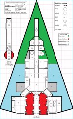
And it looks like this:
SWorkAHL1JPG.jpg

Description of interior details by location to follow in the next post.
 
Last edited:
Interior details by location:

Note that some location numbers are presented out of sequence because I retained the original designations where possible, and re-used designations for deleted spaces.

1. Avionics Bay. This provides maintenance access to the bridge's sensors and communications equipment. It's cramped in there; it's only 1.5m tall at the access panel from the cockpit (2), and less than 1m tall at the nose end. The floor hatch allows maintenance crews to access this space, but is normally manually locked from inside. This compartment, which shares pressurization with the bridge, can be used as an exit airlock in an emergency, but lacks the filtration/steriliaton equipment normally present in exterior airlocks.

2. Bridge. It's more of a cockpit, really. The two seats are on raised platforms on either side of the central aisle, and there is little overhead clearance above them. The space between the two control panels is the projection area for a holographic display, behind which is the access panel to the avionics bay (1).

2a. Computer. The ship's Model/1bis computer is located here, accessible through a normally-locked hatch.

15. Ship's Lockers, Forward. (Yes, I know it's out of sequence. It'll get worse shorty.) These two lockers hold vacc suits, adverse weather gear, and assorted small arms. There is additional "Ship's locker" storage in the cargo bay (13).

20. Personnel Airlock. Has both dorsal (top) and ventral (bottom) exits. Ventral exit is served by a ladder extended from the nose landing gear door. The adjacent "inert machinery" is a full suite of air filtration and decontamination equipment for processing hostile atmospheres and chem/bio/radiological contamination.

3. Central Corridor. This corridor leads from the cockpit (2) past the forward ship's lockers (15) personnel airlock (20) and crew staterooms (4-7) to the common area (8). The ceiling iris valve leads to the front of the upper gallery (19).

4-7. Staterooms 1-4. Each contains a bed (with a second, stowable bed above it for double occupancy), chair, desk, closet and drawers, and a basic fold-away fresher. Stateroom 1 (location 4) is usually the mission leader/pilot's room, and includes a wall safe.

8. Common Area. This room contains the kitchen and mess area, as well as storage for rations and perishables (8b). It also has recreation equipment and folding furniture. Adjacent to it is a shared full washroom with shower facilities (8a).

9. Fuel Tanks. Not normally accessible from the interior. This is just as well, as they normally contain liquid hydrogen, which is lethally cold as well as potentially flammable/explosive in the presence of oxygen.

10. Main landing Gear. There is a third (nose) gear, not shown.

11. Access to Aft Storage and Parking. These airlocks (11a and 11b) each have the full suite of air filtration and decontamination equipment for processing hostile atmospheres and chem/bio/radiological contamination, for when it is impractical to decontaminate the cargo hold and/or air/raft bay.

12. Drive Bay. Contains the maneuver and jump drives, and power plant. Tools and test equipment are stored in the ceiling. The ship's Maker Device is beneath the deck paneling. The ceiling hatch, forward, leads to the internal airlock (18).

13. Cargo Hold. Three displacement-tons capacity. The manual floor hatch opens to the underside of the hull, and there is a retractable ladder present. Additional "ship's locker" storage is present along the outboard bulkhed. These cabinets are airtight when closed and latched, but are only as durable as ordinary interior partitions, not interior bulkheads. Cargo hold can be used as an airlock, has the full suite of decon equipment.

14. Air/Raft Bay. Holds one standard Air/Raft. The standard IISS Air/Raft carries an ablative-foam re-entry aerobraking kit, and at least one spare kit is kept on board ship. Bay can be used as an airlock, has the full suite of decon equipment.

15. Ship's Locker. Distributed between the cargo hold (13) and the forward end of the central corridor (3).

16. Turret. Normally a double turret, provided to Detached Duty personnel unarmed. Couriers typically have a laser and missile launcher; explorers, two missile launchers (with drone missiles in addition to normal ordnance). Sandcasters are recommended in general since the Type S is a poor combatant vessel.

17. Storage. Additional ordnance for the turret (16) can be stored here for convenience, but complicates passage through the crawl space (19).

18. Internal Airlock. Provides access to ordnance storage (17), the turret (16), and the drive bay (12). Does not have air decon equipment, as it is primaraly meant to allow passage between pressurized and unpressurized compartments during space operational contingencies.

19. Upper Gallery. Provides access to sensor electronics to either side of the central crawlspace. 1.5m tall at location 17, only 1m tall forward of there. Iris valve leads to central corridor (3).

20. Personnel Airlock. Previously described, above.
 
Last edited:
Designer's Notes:
First off, I went a little farther than necessary. The minimum required changes are the new locations 15 (forward ship's locker), 20 (forward airlock), and 2a (computer), redistributing the stateroom and common area space (4-8), and narrowing down and shortening the upper deck (16-19). The rest -- drive bay/transverse corridor/cargo and parking (11, 12, 15) is "close enough" and could have been left alone. One could reasonably move the air/raft into the larger of the aft two bays, but that's just being picky.

Second, the upper crawl space doesn't really need to be there. I included it because that pathway was present in the original version, and I wanted to keep it. The original's forward hatch to the crew quarters is now an iris valve because there isn't enough vertical clearance at the hatch's position to bring your feet under you to climb down the ladder if you're crawling toward it head-first. Since you have to approach it feet-first, you won't be able to reach the hatch mechanism. Thus, it needs to have a control pad that's in reach when you're scooting feet-first toward it, about a meter or so aft of the iris valve.

Third, I tried to keep the ship's layout close to the original in terms of exit locations and pathways and the like. I don't understand what the floor hatch in the cargo bay (13) was for since there's an iris valve at the aft end too, but left it in anyhow. And since it didn't make sense to have a cargo bay (13) with only personnel access hatches (iris valve, floor hatch) I turned the aft iris valve into a large hatch/door.

I'll probably have more to say, but this is what I recall from the design process.
 
Last edited:
With the Turret, I'm taller than 1 meter sitting in my chair at my computer.

Other than that, looks great!
Turret is a 3m sphere, inset into the hull (but not counted in the total height).

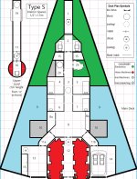
Side view section clarifies things slightly ( click here ).

Wait, wrong image. Posting from phone, will fix shortly (or in a separate post if the edit window expires).

Edit 2: it shows enough even without the turret included. The 1m height is only for most of the length -- it's 1.5m tall at the internal airlock, decreasing over the 3m ahead of that to a constant 1m height forward to the iris valve..
 
Last edited:
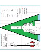
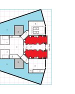
This will print full-size (1/2"=1.5m scale) on 8 1/2"x 11" paper if the margins are set to 0.25" all around, and scaling is set to 100%. You may need to set these parameters manually in your printer settings -- the default settings may have larger margins and automatic resizing.

Right-click and then Save Image As (for Firefox/Windows -- haven't tried in other op systems or browsers) to download.

Note that it clips off the nose and most of the part of the drives that stick out of the aft end, but does include all the ship's accessible interior spaces.

My next project is to do up a two-page version that includes the whole thing at this size.
S Most J.jpg
 
Do you know how I could get this to print out to 15mm (1:100) scale. Each square would be a 15mm square. I use 15mm minis and they look a lot better on 15mm/ 1:100 scale plans.
 
Do you know how I could get this to print out to 15mm (1:100) scale. Each square would be a 15mm square. I use 15mm minis and they look a lot better on 15mm/ 1:100 scale plans.
1/2" =1.5m is 1:118 scale
(probably called 1:120, as it approximates 1"=10').

Print at 84% (100÷118) and it should be close enough.
 
Last edited:
Scout/Courier (Type S): Using a 100-ton hull, the scout/courier is intended for exploration, survey, and courier duties, with many in service throughout known space. It mounts jump drive-A, maneuver drive-A, and power plant-A, giving performance of jump-2 and 2-G acceleration...

... and so on. You know this one, it's straight out of LBB2. Supplement 7 and Adventure 0 have drawings and deck plans -- it's an easily-drawn arrowhead.

There's a problem with those deck plans, though. The interior spaces simply don't fit into the hull dimensions given along with the deck plans!

So I fixed them, with a bit of help and encouragement from the commenters here.
You might find this resource (that I just found) to be an interesting jumping off point for redesign ideas. Not purely CT, but the arrangement of deck plan interior spaces looks surprisingly well thought out.
 
1/2" =1.5m is 1:118 scale
(probably called 1:120, as it approximates 1"=10').

Print at 84% (100÷118) and it should be close enough.
Note the nominal scale of 15mm figures is 1/100th. Though at this scales 120% should be fine. Note in general from plans with a 1 inch grid scaling 60% works as well.

A further note the integral bases on figures from Ground Zero Games and the Classic Citadel/RAFM figures are 1/2 inch. If that helps any.
 
Scout/Courier (Type S): Using a 100-ton hull, the scout/courier is intended for exploration, survey, and courier duties, with many in service throughout known space. It mounts jump drive-A, maneuver drive-A, and power plant-A, giving performance of jump-2 and 2-G acceleration...

... and so on. You know this one, it's straight out of LBB2. Supplement 7 and Adventure 0 have drawings and deck plans -- it's an easily-drawn arrowhead.

There's a problem with those deck plans, though. The interior spaces simply don't fit into the hull dimensions given along with the deck plans!

So I fixed them, with a bit of help and encouragement from the commenters here.
The "Forward Cargo Bay" (location 20 on the plans from Supplement 7) would be almost entirely outside the hull. So, it has to go. The "Upper Gallery" (locations 16-18) is just tall enough to be a crawl-space -- and that's after dipping down into the space above the ceiling of the crew quarters. That can stay, but it's going to be cramped. Location 19 ("a forward sensor position"), again, is almost entirely outside the hull. It's gone too. The forward staterooms (locations 4 and 5) would be clipped off at the forward outer corners at best -- leaving them more as personal sleeping niches than bedrooms. So, those went away as well, and the areas closest to the centerline got repurposed.

And it looks like this:
View attachment 3866

Description of interior details by location to follow in the next post.
It Looks Good AND Makes Sense! (Can that little grey corner in 8b be unshaded since it's not part of the landing gear? Or was that unavoidable?)
 
It Looks Good AND Makes Sense! (Can that little grey corner in 8b be unshaded since it's not part of the landing gear? Or was that unavoidable?)
I don't recall if I'd meant for it to be airlock machinery for 11b (the hallway to the Air/raft bay), or some kind of food processor. 8b is otherwise counter-top height with overhead cabinets (a kitchen counter and cooktop, basically, with a roll-down shutter cover for the whole thing to seal it during cabin depressurization and to keep stuff from floating around too much in 0g).
 
Last edited:
Back
Top