• Welcome to the new COTI server. We've moved the Citizens to a new server. Please let us know in the COTI Website issue forum if you find any problems.

CT Only: Fixing the Type S (Sulieman)

Grav_Moped

SOC-14 5K
Admin Award 2022
This started as a tangent from my chopping and splicing the deck plans of a Type S (as per S7: Traders and Gunboats) to make a 199Td, J-4/2G version of it (requiring a minor house-rule interpretation of the power plant fuel rule to recover 10Td -- YMMV, but if you don't like it you can do J4/2G in 199Td in LBB5 anyhow).

The plans are wrong -- given the stated dimensions of the hull, there are parts of the deck plans that simply cannot fit inside the hull as described and illustrated. The hull itself is "correct" per LBB2's 10-20% allowance for drafting errors -- it's 85Td, more or less. And, in my opinion, the canonical dimensions and shape look better than what'd have to be done to it to make the extraneous bits of the deck plan fit inside. Once again, I'm going to try to recover the original design for something with flawed deck plans, from an illustration (as I did with my Type T project a couple of years ago).

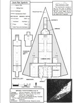
So, here we go. This is the starting point:
(Image credit: GDW/FFE)
Type S from Traders and Gunboats JPG.jpg
The first problem is that locations 19 and 20 are outside the hull dimensions if the ship's maximum height is the listed 7.5m (locations 16-18 probably fit, but at the very least 18 has a rather low ceiling).

The second one is that the two forward staterooms (locations 4 and 5) either extend outside the hull or have very low ceilings and high floors.

Surprisingly, the cockpit actually fits inside the hull (it's close, though), and the crawl-space in the nose does too (but it's about 1.5m in height at the aft end, and under 1m at the forward end).

Also, the drive bay is too small (10Td, should be 15Td) unless it's taller than the standard 3m.

In my revision, I want to keep as much of the existing deck plan, and its topology, as possible. The former suggests that there should be both dorsal and ventral exits available near the front. The latter suggests it needs a crawl-space passage from the front of the cabin to the drive bay, that bypasses most of the stateroom area.

More to come.
 
Last edited:
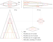
Give up on "upper galley" as anything but a crawlspace. If you want even 1 m crawlspace it can't be more than 4.5 m × 12 m, even if we assume the hull is ~100 Dt so 9 m tall:
Skärmavbild 2023-08-11 kl. 13.33.png
 
Bare minimum, the main deck MUST BE 3m in height, even if only 2.5m of that is habitable volume ... with the remaining 0.5m of deck height being devoted to services plumbing, engineering bits and bobs, life support and power lines, etc. etc. etc. (you know, all that stuff that gets "hidden in the walls" so you don't see it).

The obvious problem with the rhomboid "cone" shape we're dealing with here is that we're trying to squeeze 3 vertical decks into it.

If you want to take a fundamentalist approach (Artwork Is GOSPEL!) then THIS is a single deck starship:
t6Pc5g1.png
Reasoning as follows:
  1. A single deck starship would be 6m tall at the aft end, so as to have 1.5m of space above/below the 3m high single main deck volume on the centerline dorsal/ventral ridges of the hull.​
  2. A double deck starship would be 9m tall at the aft end, so as to have 1.5m of space above/below the 6m high double deck volume on the centerline dorsal/ventral ridges of the hull. The forward end of the interior space would be a 3m single deck while the aft end would be a 6m double deck, offset by a 1.5m (a half deck) so as to be able to fit into the available outer hull lines formed by the rhomboid pyramid shape of the outer hull.​
  3. A triple deck starship would be 12m tall at the aft end, so as to have 1.5m of space above/below the 9m high triple deck volume on the centerline dorsal/ventral ridges of the hull. The main deck would run the length of the ship's pressure hull, with the upper and lower decks confined to the extreme aft end of the hull, so as to be able to fit into the available outer hull lines formed by the rhomboid pyramid shape of the outer hull.​
If you're going to be "falling back to artwork as your starting point" for this effort, option 3 doesn't make sense from the get go, simply because it requires too much verticality to match the sleekly narrow cone/wedge shape so obviously depicted in the artwork.

AT BEST ... the drive bay is 2 decks tall, which in deck plan terms would amount to a pair of 4 squares long (fore/aft) by 4 squares wide (port/starboard) by 2 decks high (32 deck squares total) for the entire drive bay, with the A/A/A drives needing to fit inside a 6m x 6m x 6m volume of space.

Note that this would mean that translating the deck plan to the artwork (see: above) the back plates for those drives don't look square in the dorsal/ventral AND port/starboard directions. However if you look at the artwork, and the proportions in it, that's not what you see. You're not looking at a 2x2 grid of square proportions around that drive bay. You're seeing a pair of squares side by side ... a 2x1 grid of proportions on the aft end in the image. You need a rectangular vertical profile, not a square one, for the drive bay.

Therefore ... if you switch over to a single deck option, you can do a drive bay that is 8 deck squared long (fore/aft), 4 deck squares wide (port/starboard) and a single deck high (32 deck squares total) ... yielding an "aft bulkhead plate" profile of 6m wide and 3m tall that better matches the "pair of squares" side by side as seen in the image.

Consequently, I would argue ... IF starting at the artwork as the ideal to live up to with any (revised) deck plans ... then the obvious choice would be to redesign the classic Scout/Courier as a single deck starship using a rhomboid pyramid hull form factor that has a single main deck only pressure hull fitted within the lines of the outer hull. This will probably wind up making the overall dimensions change (longer fore/aft, wider port/starboard, shorter dorsal/ventral), but you'll wind up with a "sleeker" looking craft and deck plan which better represents an interior that would fit within the actual artwork.

cpp9OV6.gif


I mean ... if you're going to be "fixing" the Scout/Courier deck plans like you're proposing ... DO IT RIGHT.
Don't repeat the mistakes made previously (like putting interior spaces outside the hull when you start actually measuring stuff).

Start with a clean sheet of (graph) paper for the deck plan ... and really LOOK at the artwork you're attempting to "make work" as your starting point before making up simple line geometry drawings that will define the interior volumetric space you'll have to work with.
 
Give up on "upper galley" as anything but a crawlspace.
The "upper gallery" includes the turret fire control equipment, and at 7.5m height the aft end has up to 2.25m clearance. It is going to be a crawlspace for most of its length, and even the tallest part will have low headroom. Might be able to eke out a few centimeters of clearance by intruding into the 0.4m ceiling margin ((3m - 2.2m)/2) inside the 3m main deck, at least in the foreward-most end.

THIS is a single deck starship
Except for crawl-space and the turret fire control, yes.

The interior will be 3x7.5 for as far forward as it can be, mostly to keep as much of the existing layout as possible.

I think I'll add an "airlock room" somewhere up front with dorsal and ventral exit hatches. Ventral one is adjacent to front landing gear, so it can use a ladder attached to the gear strut.

More to come.
 
Honestly, I don't care. Meaning that there are a bunch of Scout Ship plans out there and frankly when handing out said ship I would just use which ever one I fancy at the moment.
Nothing wrong with that at all!
I'm just starting with a specific one because I needed a set of proportions and a basic interior layout from which to work. Then I got picky, as I do from time to time.
 
Honestly, to use that deckplan in the first post, I just did this: Delete the upper deck and the lower cargo hold. Don't modify them. Don't shrink them. Don't make them into a "crawlspace". Just outright remove them into non-existence. At that point room 13 is the cargo hold and ... you're done.

Note that it isn't actually accurate. The cargo hold is too big. The engine room is too small. The bridge and avionics is microscopic. (The bridge is supposed to be 1/5 of the entire ships volume!) Who knows where the computer is physically located. and the common area shouldn't even exist. But, even despite all of that, it works well enough.

But the upper and lower decks just have to go. Whoever thought they were required was obviously either high on something or didn't actually read the description of the ship.
Alternatively, repurpose the extra decks to be bridge, specifically all that extra sensor capacity. The functional equivalent of the avionics crawl space, only teaming with extra equipment for making those long range detections.
 
Cargo hold gets skinny because it's on the edge. Engine room might be taller than 3m.

But the upper and lower decks just have to go. Whoever thought they were required was obviously either high on something or didn't actually read the description of the ship.
I think they're there for RPG/ tactical combat reasons, justified because the hull is undersized so it's "fair" to add stuff. But yeah, kinda whack.
 
Alternatively, repurpose the extra decks to be bridge, specifically all that extra sensor capacity. The functional equivalent of the avionics crawl space, only teaming with extra equipment for making those long range detections.
The fundamental problem is that they're outside the hull as drawn! (Part of the upper deck can be a low but wide crawl space, but the forward cargo bay simply cannot fit.)

While you could make it look kind of like an F-35 that got hit with an ugly stick, it kind of defeats the purpose. :)
 
I'm all for trying to make a silk purse out of a sow's ear.

But unless there's some inherent stealth properties for that hull configuration, I'd go for a slightly enlarged shuttle.
 
I'm all for trying to make a silk purse out of a sow's ear.

But unless there's some inherent stealth properties for that hull configuration, I'd go for a slightly enlarged shuttle.
On my first pass with the CT/HG merge project, I thought about using Striker angled armor, and if taking a shot from the front that whole wedge works out to armor 1.

Then I woke up not wanting to sim every single angle of shots on the target and dropped it.

But, could be a why for the popularity of the wedge.
 
Take a look at the artwork on Pages 28,36, and 42 of Starter Traveller. Most of the artwork looks like a one deck ship, but the stern of the drawing on page 28 makes it look like there would be room for an abbreviated upper deck. It's much taller than the drawing in S7.
 
Revisiting this post:
Honestly, to use that deckplan in the first post, I just did this: Delete the upper deck and the lower cargo hold. Don't modify them. Don't shrink them. Don't make them into a "crawlspace". Just outright remove them into non-existence. At that point room 13 is the cargo hold and ... you're done.

Note that it isn't actually accurate. The cargo hold is too big. The engine room is too small. The bridge and avionics is microscopic. (The bridge is supposed to be 1/5 of the entire ships volume!) Who knows where the computer is physically located. and the common area shouldn't even exist. But, even despite all of that, it works well enough.
You pretty much covered my original thoughts here, except that I think the upper crawlspace is there for a reason, and I approve of that reason: it's an artifact of this being a setting for RPG/personal combat gaming, in addition to just being a rationally-designed (fictional) spacecraft. Also, the "lower cargo hold" acts as an airlock for planet-side access, and if it's going away (it will), there will need to be an actual personnel airlock somewhere. Because otherwise, there isn't one!

The "bridge and avionics" are explicitly not delineated, for what I assume are artistic reasons -- done literally, it'd look like it took up half the ship (the nose section is thin because it's pointy, so that part would have to extend pretty far back to comprise 20% of the volume).

You're right about the common area -- there's entirely too much volume committed to living space, and that in a hull that's drawn 15% smaller than it "should" be.
 
Other observations that'll go into this:
- The aft landing gear are close to what I figure would be the ship's center of mass. They're also likely too small to support the ship's weight on anything short of a reinforced pad or bedrock. So, the hull will probably settle to and sink into the ground on a regular basis. This means that the nose gear will need a significant amount of travel (vertical range) to accommodate this. Also, I need to see how much vertical clearance an underside hatch will have with the hull partway sunk into the terrain. Exiting out the top would work, but then you'd need a ladder (and someplace to stow it in the hull -- not a problem, just more setting fluff to stuff into the hull).

- There isn't a personnel airlock in the original design other than the "lower cargo bay" up front -- and that's going away. (Neither the port/aft cargo hold nor the air/raft bay are well suited to that, and you aren't going to want to expose the drive bay to hostile atmospheres.) I'll put in an "airlock room" up front, about 1.5x3m (would this be big enough? too big?) with floor and ceiling iris valves for dorsal and ventral exits. It'll be adjacent to the nose landing gear so a ladder on the gear strut can be used to get down to ground level. I don't get the feeling that this would have an elevator, but it might have a crane (winch or grav-enabled) at the port/aft cargo bay.

- Early Traveller deck plans tended toward having large staterooms, and seldom had communal washrooms even on Scout and military designs where one would expect them. I'll probably change that in the revision. And there's just too much volume committed to living space (see previous post).

- The drive bay is too small if it's a single-deck setup (10Td). The drives, as depicted, look like they aren't more than one deck high, so the engine room could be extended forward a bit, or gain some room around the edges for additional maintenance access.

- The design is the basis for the Type J Seeker, so whatever I end up changing should not preclude a similar adaptation.

Still working on this.
 
More Ways Out (doors, hatches, airlocks and such):
- For cinematic reasons, it'd be nifty to have a ramp/stairs drop out of the bottom, leading sideways. Wastes volume though.

- How would it dock to other ships, space stations, or bases on airless worlds?

- How would an injured Scout, fleeing back to the ship, get back inside without an elevator? (This is where cinematics/drama bump up against my desire for a bare-bones aesthetic for this design.)

- How would you load cargo (say, food and life support replenishment supplies)?
 
In most cases, I'd say hatches and doors take up no volume, as long as no additional equipment is attached to them beyond the door hinges, such as a two tonne space for a personnel airlock.

Doesn't mean it's free, though I took the viewpoint that the twenty tonne bridge covered the first airlock and ship's locker.

The ramp could be part of the hull, but the mechanism that raises or lowers the drawbridge, is additional.
 
Engine room - 6m ceiling instead of 3m because it includes the upper gallery engineering access. Put another way the engineering compartment is actually locations 12 and 16 combined.

You see where the 11 circle is? Make a box of hatches and have the lower hatch go down to the now aft cargo bay.
16 is access to the top of the engines. Rotate the now aft cargo bay 180 degrees.
 
- The aft landing gear are close to what I figure would be the ship's center of mass. They're also likely too small to support the ship's weight on anything short of a reinforced pad or bedrock.
That would be DUMB for a wilderness explorer/surveyor.
Remember, the Scout/Courier is the "bush plane" starship of the IISS, in the "go anywhere, do anything" tradition. Bare minimum, the landing gear ought to be able to handle unprepared terrain at austere landing sites landings (grassy field, dirt strip, etc.). Perfectly fair for "swampy ground" to still be a problem though.

Bare minimum, I would expect the landing gear to articulate when extended to unfold and create larger contact patches in order to reduce ground pressure when landed.
- There isn't a personnel airlock in the original design other than the "lower cargo bay" up front -- and that's going away. (Neither the port/aft cargo hold nor the air/raft bay are well suited to that, and you aren't going to want to expose the drive bay to hostile atmospheres.)
Actually, the air/raft berth is very nearly ideal for use as an air/lock (think about it) when bringing aboard "larger stuff" because you can use the air/raft as your grav crane for lifting stuff up into the hull.

If you want to do a ramp for walk on access, the obvious choice there would be the crossing corridor in front of the drive bay. Simply design a portion of the outboard run for that access corridor as being a "long airlock" that can rotate downwards so as to lower the floor like a ramp down to the ground. This approach works best if the aft end of the hull is only 6m tall with a single 3m deck in it, because then the rhomboid diamond cross section of the hull shape is "flatter" towards the rear and any ramp airlock for personnel access would require less of an angle of rotation to reach the ground underneath the cover of the hull above (helps keep the rain off when disembarking in wilderness locations).

Alternatively, if you take the interpretation that the entire air/raft berth is an airlock with a vehicle stuffed into it, a variety of options becomes available. Obviously, there would be the option of an aft pressure door for the air/raft to enter and exit through (although the appearance of the artwork seems to dismiss this notion), but I would argue that a vertical lift arrangement would be superior. Basically, both the floor and ceiling of the air/raft berth are pressure doors, with additional retractable pressure doors in the dorsal and ventral bulkheads of the outer hull. That way, the entire air/raft berth deck section can be a grav lift (with an air/raft stored in it) that either lowers down to the ground (to drive on/off from at ground level when landed, using the ship's hull above as shelter from radiation and precipitation, if any is present) ... OR ... the dorsal door on top of the hull opens to launch the air/raft through the dorsal opening when landed in "cluttered terrain" with obstructions around the hull at ground level. The dorsal door opening for the air/raft berth can also be used to transfer light cargoes to/from the ship via crane (grav or otherwise). Additionally, if the air/raft berth has dorsal AND ventral entry/egress, you don't need to have a door on the aft hull beside the drive bay.
Exiting out the top would work
You've going to want both ventral access (to the ground) and dorsal access (on top of the hull) because there are going to be times when the Scout/Courier is going to make water landings in oceans (for wilderness refueling, if nothing else) ... during which time the hull will partially submerge but still need to float with a net positive buoyancy so the ship doesn't sink down into the depths. Any such "topside" access hatch/airlock should be kept as far aft as practical so as to keep it above wave height in the event of water landings.

I would even go so far as to say that the best location for such an airlock would in fact be the extreme aft end of the drive bay, in between the twin drives. A single deck square bounded by bulkheads with a pressure seal forward (hatch or iris valve) into an airlock that then has vertical access points through the dorsal and ventral hull (again, hatches or iris valves) would be ideal. If you want to make life REALLY easy for crew and missions, you make that vertical access shaft a grav lift into the bargain. Doesn't change the appearance of the aft end of the hull (so no conflict with the artwork) but does give you the ideal location for a shortest distance down to the ground when landed on landing gear along with the highest point on the hull (aside from the turret dome) while partially submerged in water.
- Early Traveller deck plans tended toward having large staterooms, and seldom had communal washrooms even on Scout and military designs where one would expect them. I'll probably change that in the revision.
One thing you could do would be to make the staterooms 2x2 deck squares with a shared 1x2 fresher placed between each pair of staterooms.
Basically ... this ...

Hf2gQ54.png


Note that doing so saves all of 5 deck squares (1 per stateroom plus 1 for the corridor).
All things considered, I know that I personally would prefer (both as crew and as a passenger) for each stateroom to have its own fresher facilities ... which can still be done in a 5x5 deck squares volume limit. Just modify one of these into being 4 staterooms (and an open access corridor down the center) rather than being 3 staterooms plus a common area.

gfEWAY6.png


4 staterooms = 16 tons = 224m3 / 3 / 1.5 / 1.5 = 33.2 deck squares
33 - 25 = 8 deck squares remaining for a common area beyond the 5x5 deck squares block of staterooms and access corridor.
Note that 8 out of 33 deck squares is 24.24%, so the staterooms are in effect "pooling" ~25% of the volume allocation for each stateroom towards a common area shared by all 4 staterooms.

If you wanted to be clever, you'd put the common area FORWARD of the staterooms block and make it a 4x2 so as to put the common area between the bridge and the staterooms, allowing the hull to taper down towards the bridge forward in a way that causes less problems for the placement of deck elements inside the rectangular prism pressure hull contained inside the rhomboid pyramid shape of the outer hull (buffered by fuel tankage between the pressure hull and the outer hull).
 
Last edited:
Back
Top